Examples
From a shell to panels and connections
Explore the Cartesian manufacturing study with a panelized shell, joint imagery, and public 3DM and STL downloads.
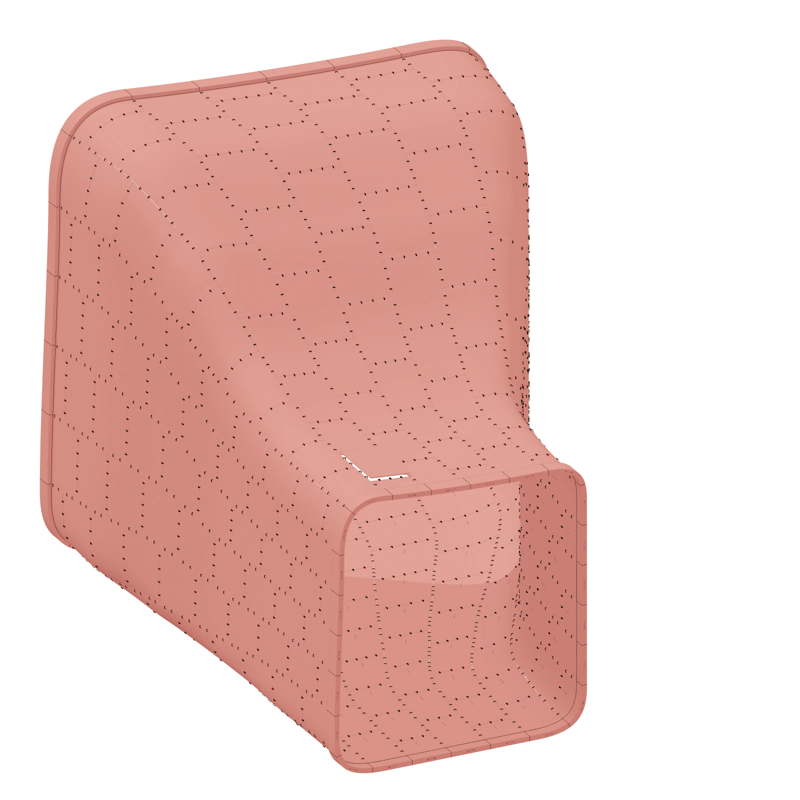
Inspect the whole and the connection
The manufacturing example pairs a shell view with a closer look at its panel connections. Looking at both scales helps you distinguish the overall surface from the way separate pieces would meet.
A shell's appearance is only one part of a fabrication study. Panel boundaries, assembly order, material thickness and access to fixings can change whether a proposed connection is workable. Keep those requirements explicit when developing the model.
Keep file size and geometry in view
This example is distributed as ZIP archives because its model files are large. Extract the archive before opening the model, allow enough storage for the extracted file, and inspect it in a tool appropriate to the representation.
Use the 3DM to inspect the panel geometry and object organisation. Check each object's actual type before choosing an editing operation. The STL provides a mesh representation for tools that require triangles.
A study is the beginning of fabrication planning
Use the model to investigate panel relationships and the connection concept. Before fabrication, establish material, machine constraints, tolerances, fastener specifications and required clearances. Validate those choices against the model and the production process.
The published files are not manufacturing certification. In particular, a downloadable surface model does not establish structural adequacy or a finished toolpath. Document the checks still needed alongside the next revision.
Inspect the model
- Download 3DM · ZIP · 84.8 MB metres · Z-up
- Download STL · ZIP · 124.6 MB millimetres · Z-up
3DM coordinates are in metres; STL coordinates are in millimetres. These are design studies. Check geometry, dimensions and fabrication requirements before production.